Fibre Optic Cables
Contents
- How fibre optic works
- Single-mode vs Multi-mode
- Single-mode (SMF)
- Multi-mode (MMF)
- Connector types
- LC (Lucent Connector)
- SC (Subscriber Connector / Standard Connector)
- FC (Ferrule Connector)
- ST (Straight Tip)
- MTP / MPO (Multi-fibre Push-On)
- E2000
- Polish types: PC, UPC, APC
- PC (Physical Contact)
- UPC (Ultra Physical Contact)
- APC (Angled Physical Contact)
- Cable construction
- Simplex vs Duplex
- Polarity
- Jacket types
- Transceivers and wavelengths
- Common mistakes
- Quick reference
- Connectors
- Colours
Fibre optic cables carry data as pulses of light through a glass or plastic core. Unlike copper, they’re immune to electromagnetic interference, can span much longer distances, and carry far more bandwidth. But the terminology around connectors, polish types, and fibre modes can be confusing. Here’s what you actually need to know.
How fibre optic works
Light travels through a thin glass core surrounded by cladding - a layer with a lower refractive index that causes total internal reflection, keeping the light bouncing along the core rather than escaping. A protective coating and jacket surround that.
Data is encoded as light pulses (on/off for 1/0) from a laser or LED source. The receiver on the other end detects those pulses with a photodiode.
Single-mode vs Multi-mode
The most fundamental distinction is between single-mode (SMF) and multi-mode (MMF) fibre.
Single-mode (SMF)
- Core diameter: 9 µm
- Uses a laser source
- Carries one mode (path) of light
- Very long distances - tens of kilometres without amplification
- Lower signal degradation
- Yellow jacket by convention
- More expensive transceivers
Single-mode is used for long-haul runs: between buildings, ISP infrastructure, undersea cables, datacenter interconnects across a campus.
Multi-mode (MMF)
- Core diameter: 50 µm (OM3/OM4/OM5) or 62.5 µm (older OM1/OM2)
- Uses an LED or VCSEL (vertical-cavity surface-emitting laser)
- Carries multiple modes of light simultaneously
- Shorter distances - typically up to 300–550 m at 10 Gbps, less at higher speeds
- More modal dispersion (modes arrive at slightly different times, broadening pulses)
- Orange (OM1/OM2/OM3) or aqua (OM4) or lime-green (OM5) jacket
- Cheaper transceivers
Multi-mode is used for short runs inside buildings and datacenters where cost matters more than distance.
| Type | Core | Max distance (10G) | Colour |
|---|---|---|---|
| OM1 | 62.5 µm | 33 m | Orange |
| OM2 | 50 µm | 82 m | Orange |
| OM3 | 50 µm | 300 m | Orange/Aqua |
| OM4 | 50 µm | 550 m | Aqua |
| OM5 | 50 µm | 550 m (SWDM4) | Lime green |
| OS1/OS2 | 9 µm | 10 km+ | Yellow |
Connector types
The connector is the physical plug that terminates a fibre cable. Each type has different form factors, locking mechanisms, and common use cases.
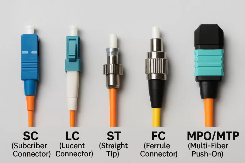
LC (Lucent Connector)
The most common connector in modern datacenters and SFP transceivers. Small form factor with a push-pull latch (similar to an RJ45 tab). Available as simplex (one fibre) or duplex (two fibres in a clip). The small size is why SFP and SFP+ modules use LC - you can fit more ports in a dense switch.
SC (Subscriber Connector / Standard Connector)
Larger square-bodied connector with a push-pull coupling. Very common in telecom and older datacenter equipment, still widely used in passive optical networks (PON/GPON). Snap-in design. Available simplex or duplex. Easier to handle than LC for field work.
FC (Ferrule Connector)
Round threaded connector that screws in to lock. Very secure and vibration-resistant, making it common in test equipment, optical instruments, and environments with vibration. Less common in datacenters.
ST (Straight Tip)
Bayonet-style connector - push and twist to lock, like a BNC. Older design, mostly found in legacy installations and some industrial equipment.
MTP / MPO (Multi-fibre Push-On)
A high-density connector housing 8, 12, or 24 fibres in a single ferrule. Used for backbone cabling, high-density patch panels, and breakout cables. An MTP is the commercial name (by US Conec) for a specific improved version of MPO.
Common use: a 12-fibre MTP cable from a switch to a breakout cassette, which fans out to 6× duplex LC or SC connectors.
E2000
Spring-loaded shutter that protects the ferrule automatically when disconnected. Common in telecom applications and FTTH (fibre-to-the-home) in Europe.
Polish types: PC, UPC, APC
The ferrule tip - the glass end-face - is polished to minimise reflections. The polish type matters a lot for signal quality.
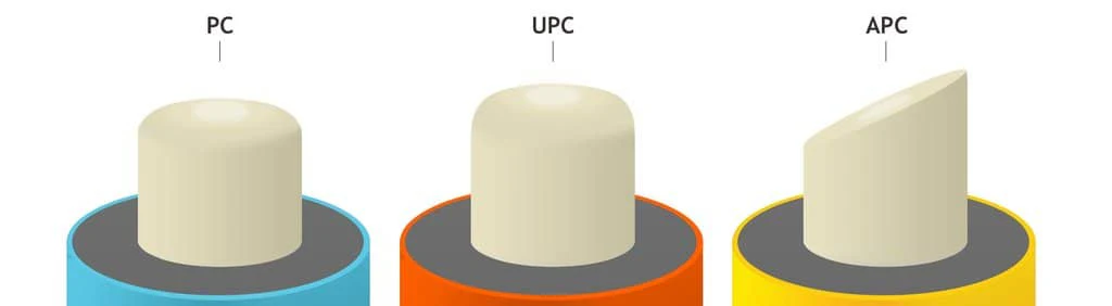
PC (Physical Contact)
Slightly curved (convex) end-face so the fibres make physical contact in the centre, avoiding an air gap. Typical return loss (reflected signal): -40 dB. The curved polish reduces back-reflection compared to a flat face.
UPC (Ultra Physical Contact)
An improved version of PC with a finer surface finish and tighter curve. Typical return loss: -50 dB to -55 dB. The standard choice for most datacentre and LAN applications. Blue boot/housing by convention.
APC (Angled Physical Contact)
The end-face is polished at an 8° angle to the ferrule axis. Any reflected light goes off at an angle and doesn’t travel back down the fibre. Typical return loss: -60 dB to -70 dB.
APC is required when back-reflections would cause problems - GPON/FTTH networks, analogue cable TV overlay (RF over fibre), and high-precision test equipment. Green boot/housing by convention.
Critical point: UPC and APC are physically incompatible. Connecting an APC to a UPC connector will damage the angled ferrule and cause signal loss. The green vs blue colour coding exists precisely to prevent this. Always check before mating.
| Polish | Return loss | Colour | Use case |
|---|---|---|---|
| PC | -40 dB | - | Legacy/basic |
| UPC | -50 to -55 dB | Blue | Datacentre, LAN, general |
| APC | -60 to -70 dB | Green | GPON, FTTH, analogue overlay |
Cable construction
Simplex vs Duplex
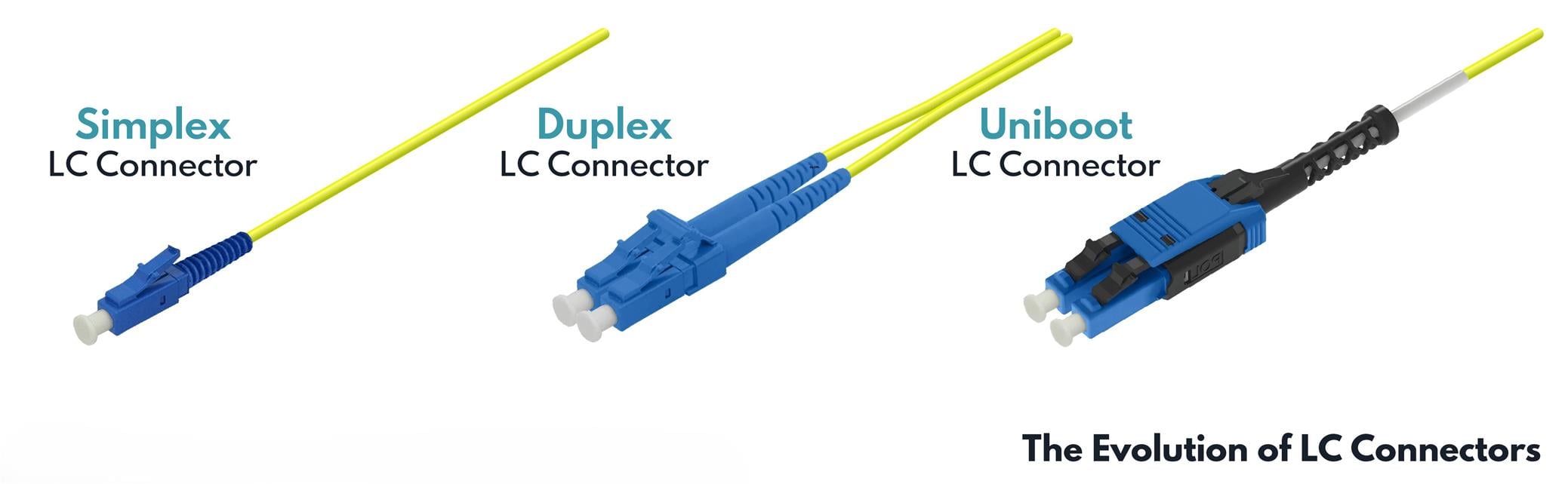
- Simplex: single fibre, one-way transmission. Used where TX and RX are on separate fibres in separate cables, or for BiDi (bidirectional) transceivers.
- Duplex: two fibres side by side in a zip-cord jacket. Standard for most transceivers that use separate TX and RX fibres.
- Uniboot: a duplex cable with both fibres in a single round jacket and a single LC connector housing. Physically looks like a simplex cable but carries two fibres. Common in high-density patching - takes up less space in a bundle, and many uniboot connectors allow the polarity to be reversed in the field by swapping the fibre positions inside the boot without reterminating.
Polarity
With duplex fibre, one fibre carries TX and the other RX. Polarity defines which fibre connects to which. Get this wrong and you’ll have a link that’s up on one side but not the other, or no light received at all.
TIA-568 defines three polarity methods (A, B, C) for structured cabling. Most simple direct-attach connections just need a crossover - the patch cable connects TX on one end to RX on the other, which a standard duplex patch cord with LC does automatically if both ends have the same connector orientation.
Jacket types
- LSZH (Low Smoke Zero Halogen): required in enclosed or poorly-ventilated spaces. Doesn’t produce toxic halogen gases when burning.
- Plenum (CMP): for air-handling spaces (dropped ceilings, raised floors used as return air). Flame-retardant, low-smoke.
- Riser (CMR): for vertical runs between floors.
- OS2 vs OS1: OS2 is tighter-buffered and supports longer distances; OS1 is loose-tube, more common outdoors.
Transceivers and wavelengths
Most short-range SFP transceivers use 850 nm (multi-mode) or 1310 nm (single-mode). Longer-range single-mode uses 1310 nm or 1550 nm.
BiDi (bidirectional) transceivers put TX and RX on a single fibre using different wavelengths - typically 1310/1490 nm or 1270/1330 nm. They come in matched pairs; you can’t mix two of the same model at each end.
DWDM (Dense Wavelength Division Multiplexing) packs many channels onto a single fibre using closely-spaced wavelengths around 1550 nm, allowing a single fibre pair to carry 40, 80, or more independent 10G/100G/400G channels.
Common mistakes
Mixing UPC and APC - as above, they’re physically incompatible and the damage isn’t always obvious. Check the colour before plugging in.
Bending past the minimum bend radius - fibre breaks or micro-bends cause loss. Don’t zip-tie tightly, don’t route sharp corners.
ITU-T G.657 defines bend-insensitive single-mode fibre categories with progressively tighter minimum bend radii:
| Category | Min bend radius (1 turn) | G.652.D compatible |
|---|---|---|
| A1 | 10 mm | Yes |
| A2 | 7.5 mm | Yes |
| B2 | 7.5 mm | Not required |
| B3 | 5 mm | Not required |
The A series is backward-compatible with standard G.652.D single-mode fibre - you can mix A1/A2 with regular SMF infrastructure without issues. The B series achieves tighter bends by using a different refractive index profile, but that change means it may not be fully interoperable with G.652.D fibre (higher splice/connector loss is possible). B3 is used in the tightest installations such as FTTH drop cables routed inside walls and conduit bends.
Standard G.652.D fibre (not G.657) has a minimum bend radius of around 30 mm - which is why that number is often cited as “the minimum” for generic patch cables. Exceeding the minimum doesn’t always cause an immediate break; it causes micro-bending loss that shows up as degraded signal or intermittent errors.
Dirty connectors - fibre end-faces collect dust and oils. A single particle on the ferrule can scatter the beam. Always inspect with a fibre inspection scope before connecting, and clean with dry/wet lint-free wipes or a click-cleaner. “Inspect before you connect” is a real rule, not just advice.
Wrong fibre type for the transceiver - plugging a multi-mode cable into a single-mode transceiver (or vice versa) won’t necessarily cause a visible error immediately, but signal quality will be terrible and link distances will be wrong. Match fibre type to transceiver spec.
Polarity issues - if a link won’t come up and the hardware is correct, swap the TX/RX fibre pair at one end.
Quick reference
Connectors
| Connector | Size | Lock | Common use |
|---|---|---|---|
| LC | Small | Latch | SFP/SFP+, datacenter |
| SC | Medium | Push-pull | PON/GPON, telecom |
| FC | Round | Threaded | Test equipment, instruments |
| ST | Round | Bayonet | Legacy, industrial |
| MTP/MPO | Multi-fibre | Push-pull | High-density backbone |
| E2000 | Medium | Spring shutter | Telecom, FTTH Europe |
Colours
Boot/housing colour indicates polish type and fibre mode - not connector type:
| Colour | Meaning |
|---|---|
| Blue | UPC - single-mode |
| Green | APC - single-mode |
| Beige / cream | PC - multi-mode |
| Aqua | Multi-mode OM3/OM4 (cable jacket) |
| Yellow | Single-mode OS1/OS2 (cable jacket) |
| Orange | Multi-mode OM1/OM2/OM3 (cable jacket) |
| Lime green | Multi-mode OM5 (cable jacket) |